Gosund WP5

The Gosund WP5 is a cheap WiFi smart plug. I bought a 4 pack from Amazon during a sale for about $22 CAD. Internally, it uses the ESP8285 chip and is compatible with Tasmota.
Before you buy these however, be aware that you cannot load Tasmota over the air at the moment (if ever). The tuya-convert project has detailed the issue on their Wiki, but it boils down to the PSK key that is used to communicate with the stock firmware to initiate a OTA update is now generated during the production of the plug at the factory rather than something that is generated algorithmically. You can still load Tasmota if you physically open up the plugs and connect to the serial pins of the ESP chip, something which I will document below.
Tinkering

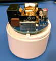
Open the WP5 by prying on the back side of the plug, separating the outer casing from the inner circular plate. RubyBailey1 in his Instructables article suggests using some nails cut to length and inserted into all 3 prongs and hammering down to separate the casing from the back plate. However, this method will put a considerable amount of force on the PCB. I opted to just spudger my way in with some tiny flat headed screwdrivers. This will bend the outer casing, but can be mostly repaired by applying some hot air later. Imaged on the right is how it looks after prying apart the casing and then repairing it with some hot air.

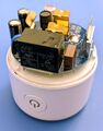
To interact with the ESP8285 chip, we need access to 5 pins: the TX/RX serial, Vcc, ground, and GPIO0. Because the ESP8285 chip is soldered directly to the main board, these pins can only be accessed from the bottom of the PCB. Access to the underside of the PCB however, requires desoldering the connections to the mains prongs. Fortunately, Vcc is exposed as a test pad, ground is exposed at various places including the shielding on the ESP, and GPIO0 is exposed as test pad on the rear side of the chip. TX/RX can be accessed by carefully positioning some wires and affixing it with some tape.
With some help with some helping hands, I was able to rig together something that connected all 5 pins as shown on the left.

Entering UART bootloader / programming mode
Like the other ESP8266 chips, you can enter the UART bootloader (aka. flash or programming mode) by grounding GPIO0. For more information, see ESP8266 Boot Modes. In the Gosund WP5, GPIO0 is exposed as a test point labeled IO0 on the rear side of the board. Ground this when powering on the chip will bring the ESP into this mode.
The ESP chip when loaded into this mode will draw approximately 0.11 watts instead of the usual 0.26 watts and gives a good indication of which mode the chip is in.
Dumping stock firmware
Use esptool to read the firmware. Run the following command to extract the firmware from the ESP chip.
$ python -m esptool --port /dev/ttyUSB0 --baud 115200 --chip auto read_flash  0 0x100000 firmware.bin
esptool.py v3.0
Serial port /dev/ttyUSB0
Connecting...
Detecting chip type... ESP8266
Chip is ESP8285
Features: WiFi, Embedded Flash
Crystal is 26MHz
MAC: c4:dd:57:03:53:c0
Uploading stub...
Running stub...
Stub running...
1048576 (100 %)
1048576 (100 %)
Read 1048576 bytes at 0x0 in 95.5 seconds (87.8 kbit/s)...
Hard resetting via RTS pin...
After obtaining the firmware, you can extract the stock PSK key by running strings on the binary. This information might be useful for the tuya-convert community to help them potentially finding out how the PSK keys are generated.
Digest mismatch issue
When trying to dump the firmware with esptool, I kept getting a digest mismatch error:
$ python -m esptool --port /dev/ttyUSB0 --chip auto read_flash  0 0x100000 firmware.bin
esptool.py v3.0
Serial port /dev/ttyUSB0
Connecting........_____....._
Detecting chip type... ESP8266
Chip is ESP8285
Features: WiFi, Embedded Flash
Crystal is 26MHz
MAC: c4:dd:57:0d:2c:de
Uploading stub...
Running stub...
Stub running...
1048576 (100 %)
1048576 (100 %)

A fatal error occurred: Digest mismatch: expected 9B60686A442B0A68591CFB54D28B867B, got 458345CAB9C61F97AAB45943ED64C234
Using a slower speed (9600 baud) worked. The issue was intermittent probably because of a sketchy serial connection.
Loading Tasmota
Download the most recent version of Tasmota from http://ota.tasmota.com/tasmota/release/. Using esptool, erase and then flash the firmware.
$ python -m esptool --port /dev/ttyUSB0  erase_flash
esptool.py v3.0
Serial port /dev/ttyUSB0
Connecting........_____....._____....._____...
Detecting chip type... ESP8266
Chip is ESP8285
Features: WiFi, Embedded Flash
Crystal is 26MHz
MAC: 70:03:9f:89:68:a6
Uploading stub...
Running stub...
Stub running...
Erasing flash (this may take a while)...
Chip erase completed successfully in 0.9s
Hard resetting via RTS pin...

## Reset and bring device back into flash mode
$ python -m esptool --port /dev/ttyUSB0 write_flash -fs 1MB -fm dout 0x0 tasmota.bin
esptool.py v3.0
Serial port /dev/ttyUSB0
Connecting........__
Detecting chip type... ESP8266
Chip is ESP8285
Features: WiFi, Embedded Flash
Crystal is 26MHz
MAC: 70:03:9f:89:68:a6
Uploading stub...
Running stub...
Stub running...
Configuring flash size...
Compressed 613568 bytes to 438208...
Wrote 613568 bytes (438208 compressed) at 0x00000000 in 38.7 seconds (effective 126.9 kbit/s)...
Hash of data verified.

Leaving...
Hard resetting via RTS pin...
Troubleshooting
Esptool cannot connect
When trying to dump the firmware from the ESP, I kept on getting this error message:
Unsupported Command Error received. Probably this means Secure Download Mode is
enabled, autodetection will not work. Need to manually specify the chip.
After trying a few more times, it started working. It is most likely a sketchy connection that's causing this issue. Ensure the TX/RX pins are connected securely. This was fixed by redoing my serial connection again and making sure the tx/rx pins had a good connection.
Images
-
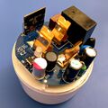
 Gosund WP5 ESP8285 chip, front
 -
 Gosund WP5 relay
 -
-
-


See Also
- Tasmota template, listing GPIO pins: https://templates.blakadder.com/gosund_WP5.html
- Guide on opening the WP5: https://www.instructables.com/Downloading-Tasmota-Onto-a-Gosund-WP5-or-WP3-Smart/
- A teardown of the WP5: https://vmallet.com/2020/07/gosund-wp3-smart-plug-teardown-and-schematic/
- esptool: https://github.com/espressif/esptool
| ||||||||||