SSD
A SSD (short for solid-state drive) uses integrated circuits to store data persistently. Unlike traditional spinning hard disks, a solid-state disk has no moving parts.
Hardware
Controller
The SSD controller provides an interface to the NAND flash memory and has a significant impact on the SSD performance. Other tasks that are dealt with by the controller are:
- Bad block mapping
- Read/write cache
- Encryption
- Error detection / correction
- Garbage collection
- Wear leveling
Memory
Operation
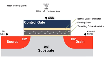
SSDs use flash memory to retain data. Flash memory stores information in an array of memory cells constructed from floating-gate transistors (Floating-Gate MOSFET, or FGMOS). The floating-gate is a gate that is electrically isolated and can only be altered through injection or tunneling operations.
The charge in the floating gate will affect how current flows through the transistor by partially canceling out the electric field from the control gate. By applying an intermediate voltage to the control gate and sensing the current through the gate, it is possible to sense and determine the value stored in the cell.
Floating-gates are erased using Fowler-Nordheim Tunneling. This is done by applying a high enough voltage between the source/drain/substrate and the control gate. Electrons in the floating gate will 'tunnel' through the oxide layer thereby erasing its value back to 1 (no electrons represents 1).
Inversely, floating-gates are written to using hot electron injection.
Single-, Multi-Level Cells
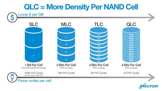
Each floating gate holds a charge. Intuitively, a cell can store a binary bit. With a smarter controller that is able to differentiate multiple charge states, higher data density can be achieved by storing additional bits in each cell. This comes at the expense of less tolerance between charge states resulting in a higher chance for errors as well as higher latencies for erasing and programming. Errors are handled by the controller using error correcting codes.
| SLC | MLC | TLC | QLC | |
|---|---|---|---|---|
| Name | Single Level | Multi Level | Triple Level | Quad Level |
| Bits per Cell | 1 | 2 | 3 | 4 |
| Charge States | 2 | 4 | 8 | 16 |
| Read latency (us) | 25 | 50 | 100 | ?? |
| Write latency (us) | 250 | 900 | 1500 | ?? |
| Erase latency (us) | 1500 | 3000 | 5000 | ?? |
| Program / Erase | 100,000 | 10,000 | 3,000 | 1,000 |
Each cell has a limited number of writes before the floating gate breaks down. In the context of whole SSDs, the number of writes before the floating gates begin to break down is represented as Terabytes Written or TBW. Terabytes Written is the total amount of data that can be written to a SSD before it is expected to fail.
Because each additional bit stored per cell will store double the amount of data stored, each additional bit will also double the expected writes per cell and thus reduce a cell's life by half. Therefore, a QLC SSD with 4 bits per cell will likely have half the expected writes of a TLC, a quarter of the writes of a MLC SSD, or an 8th of the writes of a SLC before failure.
Additionally, higher level cells have slower read/write times. It is typical for multi-level SSDs to come with a small amount of SLC storage for caching writes.
For the precise TBW values that a particular SSD has, refer to the SSD's data sheet. For example, a 2TB Western Digital Blue 3D NAND (WDS200T2B0A) has a TBW endurance of 500TB, while a higher end Samsung 860 PRO 512GB has a TBW endurance of 600TB, or about 5x more by capacity.
See also:
- https://semiconductor.samsung.com/resources/warranty/SAMSUNG_SSD_Limited_Warranty_English_UK.pdf - Samsung's TBW values
Types
While there are two common types of non-volatile flash memories (NAND and NOR), nearly all SSDs today use NAND flash.
NOR flash cells are connected in parallel and acts like a NOR gate. Reading a particular cell requires all other cells in the arrangement to be turned off so that no current flows except through the cell that is being read.
NAND flash bit cells are connected in series and acts like a NAND gate. Reading a particular bit cell requires all other bit cells in the arrangement to be turned on so that they allow current to flow freely except for the cell that is being read. Writing a particular bit requires all other bits in the arrangement to be rewritten.
NAND flash memory is cheaper because cells can be chained in series rather than NOR where cells are in parallel. There is also less wiring required for NAND cells which increases data density. Higher densities can be achieved by stacking these NAND memory arrays on top of each other (3D-NAND)
Host Interfaces
| Interface | Speed |
|---|---|
| SAS, Serial attached SCSI | 12.0 Gbit/s with SAS-3 |
| Parallel SCSI | 0.04+ Gbit/s |
| SATA, Serial ATA | 6.0 Gbit/s with SATA 3.0 |
| Parallel ATA | 1.064 Gbit/s with ATA-4/UDMA |
| PCI Express | 31.5 Gbit/s with PCIe 3.0 x4 |
| M.2 | 31.5 Gbit/s for PCIe 3.0 x4, 6.0 GBit/s with SATA 3.0 |
| U.2 | 31.5 Gbit/s with PCIe 3.0 x4 |
| Fibre Channel | 128 Gbit/s with 128GFC "Gen 6" |
| USB | 10 Gbit/s with USB 3.1, 5 Gbit/s with USB 3.0, 0.48 Gbit/s with USB 2.0 |
Protocols
Two main protocols
- AHCI - Advanced Host Controller Interface. Used by SATA based drives.
- NVMe - Non-Volatile Memory Express. Tailored specifically for PCIE-based drives.
In terms of performance, NVME SSDs performs better with higher IOPS because of more command queues in parallel. For comparison, AHCI can process up to 32 commands with one command queue while NVME has up to 65,000 command queues with up to 65,000 commands per queue.
Reliability
SSDs store data as electrical charges in floating gates. This charge will slowly leak over time without power. Old drives may start losing data after 1-2 years in storage, depending on temperature and P/E cycles.
Crypto
SSDs with encryption support (self-encrypting drives, or SEDs for short) contains a dedicated AES co-processor to offload encryption and to avoid negatively impacting data throughput. Encryption uses the disk encryption key (DEK) which can be password protected. The password for a DEK can also be changed without needing to re-encrypting the entire contents of the drive. With encryption enabled, data can be protected by protecting the DEK or wiped by erasing the DEK.
ATA Security is the original standard for ATA (IBM PC/AT Attachment) storage devices. It defines the security feature set which allows for locking and unlocking with a password. SEDs (ab)used the ATA security password for encryption.
TCG (Trusted Computing Group) Opal is the newer specification for SEDs. The protocol is layered on top of ATA or NVMe and mandates AES-128 or AES-256. Multiple passwords can be defined. A storage device can be divided into multiple locking ranges that can be locked or unlocked independently with each encrypted with a different DEK (Media Encryption Key in Opal terminology). A global range is defined to cover all sectors. Multiple passwords can be assigned permissions to unlock particular ranges.
Garbage Collection & TRIM
SSDs store data in fixed-size chunks called pages and are typically the entire row within a NAND memory grid. These pages are then arranged in larger groups called blocks. SSDs can read at a per-page level, but can only write at a per-block level. In order to update a value within a page, the controller must first read the entire block into memory, erase the block, then re-write the contents with the updated page back. Updates could be made faster if the controller can mark a page as stale and then writing the updated page elsewhere. Garbage collection done by the controller can then run in the background during idle periods to re-write and erase blocks with stale pages elsewhere.
The TRIM command notifies the controller which pages are no longer in use and can be erased. When the SSD rewrites blocks (eg. during Garbage collection), it will ignore these unused pages when writing these blocks, resulting in less write amplification and higher write throughput.
Linux
Linux 2.6.28 supports TRIM for EXT4, BTRFS, FAT, GFS2, JFS, and XFS. EXT3, NILFS2, OCFS2 offer ioctls for offline TRIMs.
# fstrim -a -v
Flags:
-aflag tells fstrim to check all available valid partitions-vfor verbose
Some distributions will already have this enabled by default. You can add this to the weekly crontab at /etc/cron.weekly/fstrim.
Windows
Windows 7 supported TRIM in AHCI and legacy IDE/ATA modes. Windows 8 and later support TRIM for PCI Express on NVMe.
## Enable
fsutil behavior set disabledeletenotify 0

## Disable
fsutil behavior set disabledeletenotify 0


