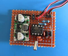
ATtiny85
The ATtiny85 is an Atmel 8-bit AVR microcontroller. The ATtiny falls under the tinyAVR series of AVR controllers and is more limited in terms of available memory, IO pins, and peripheral sets when compared to the megaAVR series microcontrollers found in many Arduinos. However, the ATtiny trades these limitations for lower power consumption and smaller form factor.
A single ATtiny85 IC costs around $3-4 CAD shipped from China which seems quite expensive when compared to something like the ESP8266. A 5 pack I bought cost about $14 CAD.
Getting started
Connecting the ATtiny for ISP
In-system programming (ISP) is used for programming the ATtiny. This is also sometimes referred to as ICSP (In-circuit serial programming).
The ATtiny85 in the DIP/SOIC/SOP package has 8 pins. The pinouts are shown on the right. To program the ATtiny, we will be using ISP via pins 5, 6, and 7 (outlined in orange in the diagram). Any ISP programmer will do, but we will be using an Arudino running the ArduinoISP sketch which can be found from the examples menu.
Once the ArduinoISP sketch is programmed on the Arduino, connect the ATtiny to the Arduino based on the table below.
| Arduino Pin | Function | Connect to ATtiny85 Pin |
|---|---|---|
| 10 | Reset | 1 |
| 11 | MOSI | 5 |
| 12 | MISO | 6 |
| 13 | SCK | 7 |
Connect ground and power to the ATtiny via the Arudino. You may use either 5 or 3.3 volts. A 10uF capacitor should also be connected between ground and the Arudino reset pin to prevent the Arduino from resetting during the ISP programming. At the end, it should look something like the following:
Programming the ATtiny with AVRDUDE
AVRDude (AVR Downloader/UploaDEr) is a utility that can program AVR microcontrollers using ISP. Once the appropriate connections are made, we can use avrdude to read/write to the microcontroller.
avrdude takes some required options:
-c programmer-id- specify the programmer you are using. When using the Arduino as the ISP programmer, you may use theavrisporarduino(which appears to be aliases forstk500) as the programmer.-p part-number- the board you are targeting-P port- the device or port that is connected to the ISP programmer. On Windows, it is probably someCOM#port. On Linux, it's likely to be/dev/ttyUSB#.-B bit-clock- Used to adjust the SPI speed. Default is 10, for 100KHz. KHz = 1000/(1.5+B).
Some useful commands to be aware of:
| Task | Command |
|---|---|
| Read fuse settings | avrdude -c avrisp -b 19200 -p attiny85 -P /dev/ttyUSB0 -U lfuse:r:-:i
|
| Change fuse settings | avrdude -c avrisp -b 19200 -p attiny85 -P /dev/ttyUSB0 -U lfuse:w:0xXX:m -U hfuse:w:0xXX:m -U efuse:w:0xXX:m
Be careful when setting the fuses for an external clock. You may need to adjust the SPI speed in your programmer or via the -B option in avrdude. |
| Write flash | avrdude -c avrisp -b 19200 -p attiny85 -P /dev/ttyUSB0 -U flash:w:firmware.hex
|
| Reading flash | avrdude -c avrisp -b 19200 -p attiny85 -P /dev/ttyUSB0 -U flash:r:readout.hex:r
|
Other notes
ATtiny configuration fuses
There are some configuration settings that can be set on the ATtiny. These settings can change the behavior of the microcontroller such as changing its clock speed or using an external clock source.
Despite its name, these fuses are really just flash/EEPROM values used as configuration parameters. You may change these values at a later time and are values don't actually blow any fuses.
There is a fuse calculator at https://www.engbedded.com/fusecalc/ for a wide array of AVR microcontrollers.
Comparison with other ATtiny microprocessors
The distinction between the other ATtiny microprocessors are:
| ATTiny25 | ATTiny45 | ATTiny85 | |
|---|---|---|---|
| Programmable Flash Memory (10k write/erase) | 2K | 4K | 8K |
| EEPROM (100k write/erase) | 128 bytes | 256 bytes | 512 bytes |
| SRAM | 128 bytes | 256 bytes | 512 bytes |
| Program Counter bits wide | 10 | 11 | 12 |
Tasks
Implementing the crazy clock with an ATtiny85
The crazy clock project at https://github.com/nsayer/Crazy-Clock uses an ATtiny85 to change the behavior of clock movements driven by a lavet stepper motor. This is done by disconnecting the microcontroller in these clock movements and connecting the lavet stepper motor directly to the ATtiny85. This project includes some interesting clock behaviors such that ticks happen irregularly while still maintaining time overall.
To reduce power consumption, an external 32.768KHz clock is used with the ATtiny85. Two pins are used to drive the lavet stepper motor.
Quick guide
The bill of materials to get your own crazy clock are:
- 2x Schottky diodes
- 2x 100 Ohm resistors, 1x 10K resistor
- 2x ~15 pF capacitor
- 1x 32.768KHz crystal
- 1x ATtiny85
- ISP programmer (an Arduino would do)
- A random clock that uses a lavet stepper motor
- breadboard and wires
Then,
- Clone the crazy clock git repo. Install
avrdude. - Wire up the ATtiny to the ISP programmer. Connect the crystal oscillator to XALT1/XALT2 with the 15pF capacitor on both pins tied to ground. Set the reset pin high using the 10K resistor.
- Disconnect the lavet stepper motor from the existing microcontroller in the clock movement. Connect PB1 and PB2 to the lavet stepper motor via 100 Ohm resistors. A flyback diode should be added to ground.
- Upload crazy clock to the ATtiny. This part is a little tricky since you need to change the fuses first, then adjust the programmer to use the slower SPI clock speed. First, set the fuses: After setting the fuses, make sure your programmer is using a speed of 250. If using ArduinoISP, change the line
$ make fuse#define SPI_CLOCK (1000000/6)to#define SPI_CLOCK (1500/6). For some reason,-B 250toavrdudedoesn't seem to do the trick. - Then, upload the desired clock with
make flash:This step will take a while. If your clock is connected, the second hand should be going back and forth randomly, which is sort of interesting to look at. When$ make flash TYPE=crazy
avrdudetries to verify the flash by reading back the contents, it will fail. This seems to be OK. - Seed the randomness to the EEPROM.
$ make seed
If all goes well, the clock should begin ticking using the chosen clock type.
Issues
The lavet stepper motor seems to be most happy when the ATtiny is powered via ~4v rather than 5v. When using a higher voltage, the second hand twitches but doesn't have enough power to the next second. With a lower voltage such as ~3.3v, it doesn't have enough power to reliably tick as well.
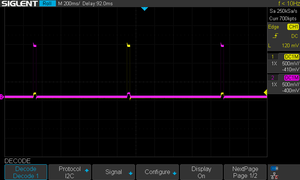
Originally, the clock uses ~32ms pulses at 1.5v every second to advance the clock. Perhaps we need to ensure the current and voltage matches?
After much fiddling and probing, the problem disappeared after I cut the trace to the original clock IC again. One of the traces might not have been severed completely which was causing an uneven current flow through the lavet motor.
Resources
- Schematics: https://hackaday.io/project/5880-crazy-clock#menu-files
- Project page: https://github.com/nsayer/Crazy-Clock
Troubleshooting
programmer not responding
When using avrdude using an Arduino running the ArduinoISP sketch as the ISP programmer, I got:
avrdude: ser_recv(): programmer is not responding
avrdude: stk500_recv(): programmer is not responding
avrdude: stk500_getsync() attempt 1 of 10: not in sync: resp=0x00
avrdude: stk500_getsync() attempt 2 of 10: not in sync: resp=0xe0
avrdude: stk500_getsync() attempt 3 of 10: not in sync: resp=0xe0
avrdude: stk500_getsync() attempt 4 of 10: not in sync: resp=0xe0
avrdude: stk500_getsync() attempt 5 of 10: not in sync: resp=0x00
avrdude: stk500_getsync() attempt 6 of 10: not in sync: resp=0xe0
avrdude: stk500_getsync() attempt 7 of 10: not in sync: resp=0xe0
avrdude: stk500_getsync() attempt 8 of 10: not in sync: resp=0xe0
avrdude: stk500_getsync() attempt 9 of 10: not in sync: resp=0x00
avrdude: ser_recv(): programmer is not responding
avrdude: stk500_recv(): programmer is not responding
avrdude: stk500_getsync() attempt 10 of 10: not in sync: resp=0x00
You need to make sure that avrdude is talking to the Arduino at 19200 baud. When calling avrdude, pass in -b 19200.
flash failes due to invalid device signature
avrdude -c avrisp -p attiny85 -B 250 -P /dev/ttyUSB0 -b 19200 -U flash:w:crazy.hex

avrdude: AVR device initialized and ready to accept instructions

Reading | ################################################## | 100% 0.04s

avrdude: Device signature = 0x000000 (retrying)

Reading | ################################################## | 100% 0.05s

avrdude: Device signature = 0x000000 (retrying)

Reading | ################################################## | 100% 0.04s

avrdude: Device signature = 0x000000
avrdude: Yikes!  Invalid device signature.
         Double check connections and try again, or use -F to override
         this check.
This happened after changing the fuses to use an external clock. Change the SPI speed in the ArudinoISP sketch to use 1500/6 if using a 32KHz oscillator with no prescaling. Change the line #define SPI_CLOCK (1000000/6) to #define SPI_CLOCK (1500/6) and reupload the ArduinoISP sketch before trying again.
See Also
- AVR Fuse Calculator: https://www.engbedded.com/fusecalc/
- Another quick start guide: https://circuitdigest.com/microcontroller-projects/attiny85-ic-programming-through-usb-using-digispark-bootloader


