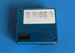
PMSA003A Dust Sensor
The PMSA003A is a laser scattering particulate sensor and is used to measure air quality. These modules can be found on Ebay for around $20 USD. Based on the datasheet, this module is capable of measuring particles as small as 0.3 micrometers.
The PMS family of particulate sensors include the PMS7003, PMS5003, and PMS1003. They all use the same serial protocol to send measurement data and receive commands.
This page will be focused on the PMSA003A sensor since that is what I currently have.
Usage
The PMSA003A uses a 1.27mm 10 pin header. This header is smaller than the usual DIP header (those are 2.54mm). Be aware that some sellers do not sell the sensor with an adapter board or the female header which makes using this module incredibly hard to do if you don't have this header.
The sensor sends data measurements in binary form over a serial connection. By default, when the sensor is powered on and enabled (with the SET pin high), it will begin transmitting readings via the Tx line at 9600 baud. You can set the sensor into a passive mode where it will only report values when commanded by sending a serial command to it (see serial section below).
Pinout
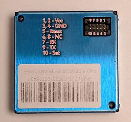
The pinouts for the unit I received appears to be different from the one described on the CityOS-air docs (which only lists 8 pins). Based on what I can find, here are the pinouts for this 10-pin model:
| Pin | CityOS Docs | Description |
|---|---|---|
| 1 | Vcc | Pin 1 is the pin closest to the corner of the module |
| 2 | Vcc | Do a continuity test to confirm the orientation. It should be the pin in the following row. See the picture above. |
| 3 | Gnd | |
| 4 | Gnd | |
| 5 | Reset | Module reset signal / TTL level @ 3.3V (reset when high, you can leave it disconnected) |
| 6 | NC | |
| 7 | RX | Serial receiver pin / TTL level @ 3.3V |
| 8 | NC | |
| 9 | TX | Serial transmission pin / TTL level @ 3.3V |
| 10 | Set | Set/enable pin / TTL level @ 3.3V (high to activate, low to suspend) |
Interfacing with the module
Raspberry Pi
As a quick test, I connected the PMSA003A to a Raspberry Pi using the following pinout:
| Function | PMSA003A | Raspberry Pi |
|---|---|---|
| 5V | 1 | 2 (5v) |
| Ground | 2 | 6 (Ground) |
| Serial transmit | 9 | 10 (UART0 RX) |
| Enable pin (set high) | 10 | 7 (GPIO 4) |
Set /dev/ttyAMA0 to 9600 baud with stty -F /dev/ttyAMA0 9600. You can then see the binary data coming in from the sensor with cat /dev/ttyAMA0. We will discuss the data format later on below.
The enable pin can be controlled by the Pi's kernel GPIO drivers. You can interact with the GPIO 4 pin by first exporting it in Linux: echo 4 > /sys/class/gpio/export and then setting the direction: echo out > /sys/class/gpio/gpio4/direction. To enable the sensor, set the GPIO 4 pin high by enabling it: echo 1 > /sys/class/gpio/gpio4/value. The sensor takes takes a short while (30 seconds?) to warm up (spin up the fan, start the laser, etc.) before any valid measurements are returned. Toggle off the sensor with echo 0 > /sys/class/gpio/gpio4/value.
Tasmota using a ESP32
Tasmota has support the PMS5003 family of sensors and should be compatible with the PMSA003A sensor in addition to the PMS7003 and PMS1003. The Tasmota driver also supports sending commands to the PMS sensor if the TX pin is connected and configured, allowing Tasmota to suspend the sensor and only poll for values periodically to lengthen its service life.
Connect the PMS sensor to the ESP32 with the following pinout:
| Function | PMSA003A | ESP32 GPIO (Tasmota Pinout) |
|---|---|---|
| 5V | 1 | Vin |
| Ground | 2 | Gnd |
| Serial transmit | 9 | GPIO 3 (PMS5003 Rx) |
| Serial receive | 7 | GPIO 1 (PMS5003 Tx) optional |
| Enable pin (set high) | 10 | 3v3 |
Once the pins are set, you should see Tasmota report the sensor values either via MQTT or from the web interface.
If you wish to poll the unit periodically and have the sensor be powered down, run the command sensor18 N where N is the desired polling interval in seconds and between 60 - 65535. Any values between 0 and 59 will result in the sensor being polled continuously.
Serial data interface
Serial interface is at 9600 baud. No check bit. One stop bit.
Reading values
The data sheet outlines what a data packet looks like. In summary, the structure of a payload is:
| Description | Offset | Length | Comment |
|---|---|---|---|
| Start header | 0 | 2 bytes | 0x42 0x4d (ASCII "BM")
|
| Frame length | 2 | 2 bytes | Frame length=2*13+2(data+check bytes) |
| PM1.0 concentration (μg/m3) | 4 | 2 bytes | CF=1,standard particle |
| PM2.5 concentration (μg/m3) | 6 | 2 bytes | CF=1,standard particle |
| PM10 concentration (μg/m3) | 8 | 2 bytes | CF=1,standard particle |
| PM1.0 concentration (μg/m3) | 10 | 2 bytes | under atmospheric environment |
| PM2.5 concentration (μg/m3) | 12 | 2 bytes | under atmospheric environment |
| PM10 concentration (μg/m3) | 14 | 2 bytes | under atmospheric environment |
| >0.3um | 16 | 2 bytes | number of particles with diameter beyond 0.3 um in 0.1 L of air. |
| >0.5um | 18 | 2 bytes | number of particles with diameter beyond 0.5 um in 0.1 L of air. |
| >1.0um | 20 | 2 bytes | number of particles with diameter beyond 1.0 um in 0.1 L of air. |
| >2.5um | 22 | 2 bytes | number of particles with diameter beyond 2.5 um in 0.1 L of air. |
| >5.0um | 24 | 2 bytes | number of particles with diameter beyond 5.0 um in 0.1 L of air. |
| >10.0um | 26 | 2 bytes | number of particles with diameter beyond 10.0 um in 0.1 L of air. |
| Reserved | 28 | 2 bytes | Reserved |
| Check code | 30 | 2 bytes | Check code is computed by adding all values into two bytes |
The module seems to print 'x's when no data is available or when it's not ready. So long as you are reading for the 'BM' header, the next 30 bytes should be data.
Sending commands
The sensor supports 3 commands (read passive, change mode, set sleep mode) with the set commands offering 2 possible data values. Each command is 6 bytes long consisting of a 2 byte header (0x424d), a 1 byte command, a 2 byte parameter, and a 1 byte check (sum of all bytes).
All possible commands and parameter combinations including the appropriate check byte are listed below.
| Command | Bytes |
|---|---|
| Active mode | 0x42, 0x4D, 0xE1, 0x00, 0x01, 0x01, 0x71
|
| Passive mode | 0x42, 0x4D, 0xE1, 0x00, 0x00, 0x01, 0x70
|
| Passive mode read | 0x42, 0x4D, 0xE2, 0x00, 0x00, 0x01, 0x71
|
| Sleep | 0x42, 0x4D, 0xE4, 0x00, 0x00, 0x01, 0x73
|
| Wake | 0x42, 0x4D, 0xE4, 0x00, 0x01, 0x01, 0x74
|
See Also
- Datasheet: https://www.evelta.com/content/datasheets/PMSA003%20series%20data%20manual_English_V2.5.pdf
- https://cityos-air.readme.io/docs/pms1003-digital-laser-dust-sensor-pm25-and-pm10
- https://cassiopeia.hk/laserdust/
- Tasmota driver: https://github.com/arendst/Tasmota/blob/master/tasmota/xsns_18_pms5003.ino

