OpenDPS

OpenDPS is an open source firmware that can run on the cheap DPS5005 (and similar) buck converters. The official project repo is at https://github.com/kanflo/opendps.
Some additional features that OpenDPS has include:
- Serial/Wi-Fi control
- A function generator (limited by hardware specs)
I have added additional features to OpenDPS including the colorful DPS-like display from the original firmware and can be found on my private repo under the dps_mode branch at https://git.steamr.com/others/opendps/-/tree/dps_mode/opendps. This adds additional features including:
- A settings screen for quick calibration adjustments
- A countdown timer
- A watt-hour meter (useful for checking how much power a battery took to charge)
Usage guide
OpenDPS is organized by separating features into different screens. By default, the firmware will start in the DPS mode screen displaying the preset voltage, current, and power. When using OpenDPS, keep in mind the following key combinations:
| Key Combination | Description |
|---|---|
| On/Off button | Turns on / off power |
| hold M1 and M2 | Calibration screen |
| SET + turn rotary | Change screens left or right |
| Hold M1 or hold M2 | In DPS mode, this will recall M1 or M2 |
| SET + M1 or SET + M2 | In DPS mode, this will set M1 or M2 to your current voltage/current values |
| Hold down rotary | Locks or unlocks the UI from unintended changes |
DPS Mode Screen
The DPS Mode screen shows the voltage, current, and power output being supplied by the power supply and was designed to look and feel as close to the original DPS firmware as possible while retaining a cleaner user interface. This feature is available through my separate branch at https://git.steamr.com/others/opendps/-/tree/dps_mode/opendps. This feature is enabled using the DPSMODE_ENABLE=1 flag when compiling.

Buttons work as you would expect: V will allow editing of the maximum voltage. A will allow editing of the maximum current.
The user interface can be locked by holding the Rotary down until a padlock symbol appears near the bottom of the screen. Conversely, the interface can be unlocked by holding the Rotary down until the padlock symbol disappears.

The third value on the screen can be changed using the Rotary Press + Rotary Turn combination. Values that are displayed in the third row can be edited using Rotary Press, or by navigating through the interface using SET + M1 or SET + M2. The DPS Mode screen currently supports editing of:
- Power Output / Power Limit
- Timer (time until power off, or time since power on)
- Brightness
- Watt-Hour Meter (measured in milliwatt-hours).

When the DPS unit is turned on, you will see either CC or CV signifying whether the device is in constant current or constant voltage mode. Depending on the power output limit that is set, a power output warning may be seen when power output exceeds 80% of the power limit. Exceeding the power limit will automatically turn the output off.

The DPS screen supports up to two recall preset settings. Each preset setting saves the voltage, current limit, power limit, and timer value. Recall a preset by holding M1 or M2. Save a preset by holding SET + M1 or SET + M2.
If a timer is set prior to power on, a hourglass icon will flash signifying that a timer is set. When the timer elapses, power will automatically be shut off. If the timer is not set prior to power on, the timer will act as a clock and will show the duration since power on.
Calibration
Voltage and current are controlled using a pair of DAC and ADCs. The two DACs control the output current and voltage while the two ADCs measure the current and voltage. You will need to calibrate these DACs and DACs in order to have accurate values.
Calibration involves finding the slope (K) and offset constant (C) of the DAC/ADC curve. The curve is linear and can be found by finding two points. For DACs, we want to map the input value to the DAC (0 ~ 4096) to the actual output value (voltage or current limits). For ADCs, we want to map the ADC output (0 ~ 4096) to its actual value (voltage or current).
Default values are defined in dps-model.h but can be changed on the fly in the settings screen.
To help calculating the appropriate K and C values, use the spreadsheet to calculate the DAC and ADC values.
Compiling and installing
Software requirements

You will need the following to get OpenDPS running on your power supply:
- A STLink or STLink clone
- A computer with OpenOCD, ARM cross compiler (
gcc-arm-none-eabi), make, and git
You may use the following Dockerfile to set up the build environment or follow the RUN step below to install the necessary dependencies.
FROM ubuntu:20.04

ARG ARM_TOOLCHAIN_URL="https://developer.arm.com/-/media/Files/downloads/gnu-rm/10-2020q4/gcc-arm-none-eabi-10-2020-q4-major-x86_64-linux.tar.bz2"

RUN set -ex; \
        apt-get update; \
        apt-get install -y wget; \
        wget -O /tmp/gcc-arm-none-eabi.tar.bz2 "$ARM_TOOLCHAIN_URL"; \
        mkdir /opt/gcc-arm-none-eabi; \
        tar -xjvf /tmp/gcc-arm-none-eabi.tar.bz2 -C /opt/gcc-arm-none-eabi --strip-components 1; \
        rm /tmp/gcc-arm-none-eabi.tar.bz2; \
        rm -rf /var/lib/apt/lists/*

# add the tools to the path
ENV PATH="/opt/gcc-arm-none-eabi/bin:${PATH}"

RUN set -ex; \
        apt-get update; \
        apt-get install -y git openocd make python netcat
Create the Docker image by placing the contents above into a Dockerfile, then build the image by running docker build -t gcc-arm-none-eabi ..
Run the image with access to your USB bus so that openocd can talk to your STLink by running:
$ docker run --rm -ti --privileged -v /dev/bus/usb:/dev/bus/usb -v `pwd`:/data gcc-arm-none-eabi bash
Hardware

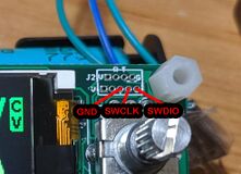
To begin, connect your STLink to the DPS as per the pinout in the picture on the right. Connect the STLink to your computer and then apply power to the DPS power supply. OpenOCD should be able to detect the device.
pi@raspberrypi:~/opendps$ openocd -f interface/stlink-v2.cfg -f target/stm32f1x.cfg
Open On-Chip Debugger 0.10.0
Licensed under GNU GPL v2
For bug reports, read
        http://openocd.org/doc/doxygen/bugs.html
Info : auto-selecting first available session transport "hla_swd". To override use 'transport select <transport>'.
Info : The selected transport took over low-level target control. The results might differ compared to plain JTAG/SWD
adapter speed: 1000 kHz
adapter_nsrst_delay: 100
none separate
Info : Unable to match requested speed 1000 kHz, using 950 kHz
Info : Unable to match requested speed 1000 kHz, using 950 kHz
Info : clock speed 950 kHz
Info : STLINK v2 JTAG v17 API v2 SWIM v4 VID 0x0483 PID 0x3748
Info : using stlink api v2
Info : Target voltage: 3.236988
Info : stm32f1x.cpu: hardware has 6 breakpoints, 4 watchpoints
Info : accepting 'telnet' connection on tcp/4444
In case your device is unique and has no support, use the bundled ocd-client.py script to generate a log file with all registers, hardware peripherals including ADC and DACs, timers, GPIOs, etc. If you are working on a supported device (that is, the dps-models.h file has mention of your model), you should be safe to skip this step.
If your device isn't listed in the dps-models.h header file, it's recommended that you create a few dumps of the device in different states (Off / On and set to different voltages) in order to make it easier to identify which GPIO pins and ADC/DACs are in use and for what purpose. The stock firmware may freeze when OpenOCD is used. The only work-around is to configure the device with the STLink disconnected and the re-connect the STLink when you are ready to create a dump. Dumps are created with ocd-client.py script like this:
$ python ocd-client.py all > dump.txt
Compiling
To compile and flash OpenDPS on your device, clone the OpenDPS repository. I will be using my dps_mode branch in the examples below, but you may substitute it with the official OpenDPS repository.
$ git clone --branch dps_mode https://github.com/kohrar/opendps.git
On the project root directory, compile OpenDPS. Specify the features that you wish to enable with a 1.
## Compile OpenDPS and then flash it on the device:
$ make -C opendps flash -j 9 MODEL=DPS5005 INVERT_ENABLE=0 CC_ENABLE=0 CL_ENABLE=0 CV_ENABLE=0 POWER_COLORED=1 POWER_OFF_VISIBLE=1 THERMAL_LOCKOUT=0  FUNCGEN_ENABLE=0 SETTINGS_ENABLE=1 DPSMODE_ENABLE=1 WDOG=1

## Flash the boot loader:
$ make -C dpsboot flash
Adjust the make flags as desired. I leave most features disabled as I prefer to only have the DPS screen and settings screen without the features.
Troubleshooting compile issues
If you get an error similar to: opendps/libopencm3/include/libopencm3/dispatch/nvic.h:8:11: fatal error: libopencm3/stm32/f1/nvic.h: No such file or directory, try running make without any arguments. This should pull in and build the libopencm3 dependency. This issue seems to be an issue with the Makefile on a clean build directory.
If your firmware doesn't appear to have the appropriate features as defined by the make flags, you may need to clear out all the objects and compiled binaries before building again. Clean up compiled objects by running: rm opendps/*.o /data/opendps/opendps/opendps_DPS5005.*
WiFi setup

You may use the TX/RX pins on the rear of the DPS unit to communicate with the OpenDPS firmware. The OpenDPS project includes a dpsctl.py script which communicates with the OpenDPS firmware using a custom binary serial protocol. Wifi control can be accomplished by using a microcontroller with a WiFi interface and serial capabilities such as the ESP8266.
While the OpenDPS project includes a custom ESP8266 firmware to act as a wifi-serial bridge, I wasn't able to get it compiling and was unhappy with the fact the WiFi AP settings had to be hard coded in. Instead, I opted to use ESP-Link which was designed exactly for this use-case.
Steps to get ESP-Link working with OpenDPS:
- Flash ESP-Link to a ESP8266 with esptool.
- Connect the ESP's TX/RX to the RX/TX pins on the first row headers (labeled T/R).
R / T pins on the first rows for receive/transmit. - Power the ESP chip with an external power supply
- Power on the ESP and configure ESP-Link to connect to your WiFi AP. Determine its IP address on your network
- Edit dpsctl.py to use TCP port 23 (rather than 5005).
Development

OpenDPS is open source and is easy to add new features.
Fonts
The Makefile is capable of rendering different fonts to be used in the firmware. Copy your .ttf or .otf font to the gfx directory and edit the Makefile. Alternatively, override the Makefile values and then run:
# make -C opendps fonts
# make -C opendps fonts METER_FONT_FILE=`pwd`/nf.ttf METER_FONT_SMALL_SIZE=16 METER_FONT_MEDIUM_SIZE=22 METER_FONT_LARGE_SIZE=30
Graphics
Convert a .png with the script:
% python gen_lookup.py -i gfx/png/poweroff.png -o poweroff
Converting gfx/png/poweroff.png to gfx-poweroff.c/h
You may need to run this inside a container as the script depends on python2 and Pillow. On a Fedora 28 docker image, run:
# yum install redhat-rpm-config zlib-devel zlib gcc python-devel @development-tools
# pip install Pillow==2.2.1
Additionally, you may encounter an error with PIL resulting in "SystemError: unknown raw mode". This requires the following change to work:
-    image_bytes = im.tobytes("raw", "RGB") # Create a byte array in 24 bit RGB format from an image
+    image_bytes = im.convert("RGBA").tobytes("raw", "RGB") # Create a byte array in 24 bit RGB format from an image