ESP8266
ESP8266 is a low cost Wi-Fi capable microcontroller created by Espressif, a Shanghai based company. There are various modules that use the ESP8266 microcontroller that are listed below.
Modules
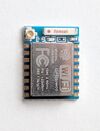
Non-exhaustive list of modules. For a complete list, see http://www.esp8266.com/wiki/doku.php?id=esp8266-module-family
For ease of use on a breadboard, an adapter board can be used which also includes a pull-up resistor for the EN pin. Each adapter board can be bought for around CAD$0.35 each.
ESP-01
ESP-01 modules expose only a couple GPIO pins. The ESP-01 package does not expose the EN pin which means you will not be able to put the chip in deep sleep and have it come back automatically.
ESP-07
These are about $2.00 USD each
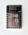
ESP-12E
These are about $1.80 USD each.
The built-in LED is on pin 2.
#define LED_BUILTIN 2
ESP-12F
The difference between the ESP-12E and the ESP-12F is the on-board antenna.
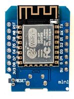
WeMos D1 Mini
These are about $3 USD and can be found for slightly less than that on AliExpress.
The WeMos D1 ESP8266 boards come with many compatible stackable sensors and modules. These boards include a micro USB port with an integrated serial connector which will automatically put the ESP8266 into the proper boot mode when flashing and properly resets the device afterwards. There is also a built in reset button which is super convenient.
Additionally, the analog A0 pin has a built-in voltage divider allowing for analog inputs ranging from 0.0V to 3.2V, rather than the ESP8266 bare chip of 0.0V and 1.0V.
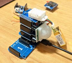
The form factor of the WeMos D1 Mini allows for additional modules to be stacked above or below and allows for very fast prototyping. To the bottom left is a picture of a stack of different sensors packed on the WeMos D1.
DHT22 Module
This module uses to D4 (GPIO 2) to communicate with the DHT22. However, since GPIO 2 is also used when the WeMos is reset, this puts the DHT22 in a weird state and will stop functioning until a full power cycle occurs.
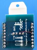
A work around is to cut off the header connecting to D4 and then bridge D4 and D3 with solder. Alternatively, break the trace on the board and solder a thin wire from the DHT22 to D3 as pictured on the right. This effectively changes the DHT22 data pin to D3 and avoids the issue that is caused when D4 is pulled high on boot.
Button Module
The button is connected to D3 and ground. There is no pull down resistor to limit current. Ensure that D3 isn't sourcing current.
BMP180 Module
Uses I2C interface connected to D1 and D2.
0.66" OLED Module
Uses I2C interface connected to D1 and D2.
Library example code: https://github.com/mcauser/Adafruit_SSD1306/blob/esp8266-64x48/examples/ssd1306_64x48_i2c/ssd1306_64x48_i2c.ino
Miscellaneous Notes
When using a photoresistor, pull A0 up to 3.3v via the photoresistor, then pull A0 down with a 10K resistor. The Wemos D1 board has a built-in voltage divider that reduces the 3.3v to 1.0v.
Quick Usage
Wiring
Skip this section if you're using a development board because all this is taken care of for you.
The ESP8266 runs on 3.3v and is not 5v tolerant. Unless you are using a development board, you must be careful when powering the board. Since serial data from TTL UART is at 5V, you must use a voltage divider or logic level converter to step the voltage down and avoid damaging the ESP8266.
Each pin can source a maximum of 12mA compared to 20-40mA for most Arduinos. There is one ADC with a voltage range of 0V to 1.0V. Do not exceed these limits or you will risk damaging the ESP8266.
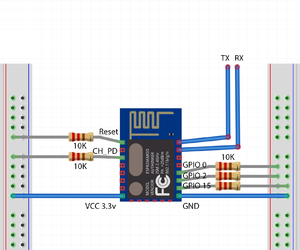
The ESP8266 can boot into one of three modes depending on the GPIO input on power up. You want to boot into the sketch by pulling GPIO 0 and GPIO 2 high with a 10K resistor to Vcc. To program the ESP8266, you will need to reboot the ESP8266 into the UART bootloader by pulling GPIO 0 down while keeping GPIO 2 high. The RST pin should also be connected to the TTL UART DTR pin via a 10K resistor so that it can be reset automatically. For flashing convenience, you may wish to connect a switch to toggle whether GPIO 0 is pulled high or low. A switch pulling RST low is also convenient to have to reset the ESP.
To power on and play with the ESP8266, connect:
| Description | |
|---|---|
| Vcc | 3.3V |
| GND | Ground |
| GPIO15 | Pull down (10K resistor to Ground) |
| GPIO 2 | Pull up (10K resistor to Vcc) |
| GPIO 0 | Pull up to boot to flash, Pull down to enter UART bootloader for flashing |
| TXD | TTL UART Rx via Logic Level Shifter or voltage divider |
| RXD | TTL UART Tx via Logic Level Shifter or voltage divider |
| RST | Pull up to run; Pull down to reset |
| EN CH_PD | Chip Power Down or the Enable pin. Pull up to run; pull down to halt.
Some modules have a built-in 10K resistor which may cause deep sleep to fail. Check by measuring the resistance manually. |
If you use an adapter board, the board might already include a couple resistors for GPIO-15 and the EN pins and can be ignored.
The ESP8266 will boot using a shared 10K pull-up resistor for GPIO 0 and GPIO 2.
A logic level shifter is required if your USB serial adapter is only 5v. Simply connect the 3.3v side to the LV (low voltage) side of the logic level shifter and the serial side to the HV (high voltage) side.
If your USB serial adapter has DTR, use 2 10K resistors to form a voltage divider and connect the reset pin between the divider for automatic reset when code is uploaded. Otherwise, reset the ESP8266 manually by shorting out the RST pin to ground while simultaneously connecting GPIO-0 to ground to enter programming mode.
Boot Modes
When wiring up your ESP, take into consideration which boot mode you wish to enter when it first powers up. It will go into one of 3 boot modes based on 3 GPIO inputs:
| GPIO15 | GPIO0 | GPIO2 | Mode |
|---|---|---|---|
| 0V | 0V | 3.3V | Uart Bootloader |
| 0V | 3.3V | 3.3V | Boot sketch (SPI flash) |
| 3.3V | x | x | SDIO mode (not used for Arduino) |
- Uart Bootloader mode is used to upload code to flash
- Boot sketch (SPI flash) mode is used to boot from flash memory
Because of the behaviors that can be induced by these GPIO pins on start up, these GIO pins shouldn't be used for peripherals without some special planning. Otherwise, you may have inconsistent boot behaviors such as having the ESP boot into SDIO/flash mode randomly.
Deep Sleep
When using ESP.deepSleep(30e6), GPIO 16 should be connected to the RST pin. The ESP8266 will wake itself up by sending a LOW to RST which will reset the device.
Software and firmware
Out of the box, the ESP8266 comes with a default NONOS firmware that accepts AT commands. For custom projects, you may choose to either use an alternative firmware such as Tasmota or write your own program using the Arduino IDE.
Which option should you use? With all the features and maturity of the firmware from the Tasmota project, I will recommend using Tasmota over writing your own sketch unless there is a strong reason otherwise. My reasoning behind this choice is that most projects involving a ESP typically just need to poll some sensors and then acting on the data which is what Tasmota is designed to do, really really well. Rather than write a bunch of custom code and pulling in all the necessary libraries for all the peripherals manually, Tasmota comes bundled with all the nice features such as Wifi Manager and most common libraries to interact with a wide array of peripherals and network protocols. Additionally, Tasmota extremely easy to change pinouts, configure WiFi, and interact with a wide range of peripherals out of the box without needing to write a single line of code..
Tasmota
See the main article on Tasmota for information on how to flash and use Tasmota.
Setting up the Arduino IDE
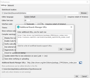
To write custom code for the ESP8266 using Arduino, you will need to add the ESP8266 boards in the Boards Manager:
- File -> Preferences -> Additional Boards Manager URLs, add: http://arduino.esp8266.com/stable/package_esp8266com_index.json
- Tools -> Board -> Board Manager -> Search for ESP8266 -> Install
- Select NodeMCU 1.0 (ESP 12-E Module)
To upload your code to the ESP8266:
- Power off the ESP8266
- Connect GPIO-0 to ground (disconnect from the 10k pull up)
- Power on the ESP8266
- Compile & Upload code in Arduino IDE
The default transfer speed is at 115200 baud which is just slow enough to be irritating. You can increase this speed without affecting the reliability of uploads.
Arduino Libraries
Some libraries that are worth checking out are:
- WiFiManager: Allows changing the AP without needing to recompile and reupload a new sketch.
- ESP8266httpUpdate: Provides ESPhttpUpdate which allows updating the ESP8266 over the air (OTA).
- FS.h: Part of the main ESP8266 Arduino core, used to interact with SPIFFS (SPI Flash File System)
- ArduinoJson: Interact with JSON
- PubSubClient: A simple MQTT client
WiFiManager
The WiFiManager library makes it easier to update the access point the ESP connects to. When the ESP boots, it connects to the previously used AP. If this fails, the ESP enters a configuration mode where it becomes an access point that can be connected to. Using a web browser, the SSID and password can be set. If successful, credentials are saved in EEPROM and the ESP will reboot.
Project website https://github.com/tzapu/WiFiManager
ESP8266httpUpdate
The ESPhttpUpdate class is part of the set of headers that are downloaded when installing the board via board manager. It allows Over-The-Air (OTA) updating by downloading a firmware from a web server.
// The line below is optional. It can be used to blink the LED on the board during flashing
// The LED will be on during download of one buffer of data from the network. The LED will
// be off during writing that buffer to flash
// On a good connection the LED should flash regularly. On a bad connection the LED will be
// on much longer than it will be off. Other pins than LED_BUILTIN may be used. The second
// value is used to put the LED on. If the LED is on with HIGH, that value should be passed
ESPhttpUpdate.setLedPin(LED_BUILTIN, LOW);

// Add optional callback notifiers
ESPhttpUpdate.onStart(update_started);
ESPhttpUpdate.onEnd(update_finished);
ESPhttpUpdate.onProgress(update_progress);
ESPhttpUpdate.onError(update_error);

t_httpUpdate_return ret = ESPhttpUpdate.update(client, "http://server/file.bin");
// Or:
//t_httpUpdate_return ret = ESPhttpUpdate.update(client, "server", 80, "file.bin");

switch (ret) {
  case HTTP_UPDATE_FAILED:
	Serial.printf("HTTP_UPDATE_FAILD Error (%d): %s\n", ESPhttpUpdate.getLastError(), ESPhttpUpdate.getLastErrorString().c_str());
	break;

  case HTTP_UPDATE_NO_UPDATES:
	Serial.println("HTTP_UPDATE_NO_UPDATES");
	break;

  case HTTP_UPDATE_OK:
	Serial.println("HTTP_UPDATE_OK");
	break;
}
SPIFFS with FS.h
You can make use of flash storage on the ESP and use it to store data. Include the FS.h header which should already exist in your Arduino IDE. Initialize the SPIFFS object and then use it to interact with files. You can create, read, and write to files like on a regular filesystem. The FS.h file can be found at https://github.com/esp8266/Arduino/blob/eea9999dc5eaf464a432f77d5b65269f9baf198d/cores/esp8266/FS.h
Storage is not erased by default when re-uploading a sketch, so any settings you save are persistent.
Learn more about SPIFFS at https://github.com/pellepl/spiffs.
ArduinoJson
Used in conjunction with SPIFFS, you can save device settings inside a JSON file and load it. ArduinoJson makes it easy to write and parse JSON data.
Project website https://arduinojson.org/
PubSubClient
A simple MQTT client.
Project website https://github.com/knolleary/pubsubclient
Other
AT Command Reference
New out of the box, the stock firmware (ESP8266 NONOS SDK) will boot and begin accepting AT commands immediately over serial at 115200 baud. You will see garbage being dumped when the ESP8266 boots because the espressif boot ROM will write a boot log at 74880 baud (https://github.com/espressif/esptool/wiki/ESP8266-Boot-ROM-Log).
See:
- https://www.espressif.com/sites/default/files/documentation/4a-esp8266_at_instruction_set_en.pdf
- https://room-15.github.io/blog/2015/03/26/esp8266-at-command-reference/
AT+RST


OK

 ets Jan  8 2013,rst cause:2, boot mode:(3,7)

load 0x40100000, len 2408, room 16
tail 8
chksum 0xe5
load 0x3ffe8000, len 776, room 0
tail 8
chksum 0x84
load 0x3ffe8310, len 632, room 0
tail 8
chksum 0xd8
csum 0xd8

2nd boot version : 1.6
  SPI Speed      : 40MHz
  SPI Mode       : QIO
  SPI Flash Size & Map: 32Mbit(512KB+512KB)
jump to run user1 @ 1000

⸮⸮⸮
ready
AT+CWMODE=3


OK
AT+CWLAP

+CWLAP:(4,"SHAW-BDF273",-73,"44:e1:37:f5:ac:c1",1,31,0)
+CWLAP:(4,"SHAW-BDF273-Guest",-70,"46:e1:37:f5:ac:c2",1,33,0)
+CWLAP:(4,"TELUS5578",-82,"28:28:5d:11:32:f4",1,16,0)
+CWLAP:(3,"Linksys11303",-72,"58:ef:68:29:64:50",1,13,0)
+CWLAP:(4,"Jazzwalz",-78,"1c:ab:c0:af:f9:f8",1,28,0)
+CWLAP:(3,"dd-wrt",-64,"10:6f:3f:e7:df:70",1,6,0)
+CWLAP:(4,"SHAW-827C50",-86,"f0:f2:49:82:7c:58",1,23,0)
+CWLAP:(3,"HP-Print-9D-Officejet Pro 8610",-84,"94:57:a5:95:cc:9d",1,25,0)
+CWLAP:(3,"Hi Clayton!",-82,"a8:4e:3f:74:52:a8",1,18,0)
+CWLAP:(3,"tl746704-EXT",-73,"02:be:f5:00:95:15",1,15,0)
+CWLAP:(3,"CSISVAN2",-83,"b8:8d:12:63:0c:c3",1,23,0)
+CWLAP:(3,"tl746704",-71,"00:25:f0:74:67:04",1,32767,0)
+CWLAP:(4,"SHAW-FC70A1",-74,"78:96:84:fb:21:99",3,26,0)
+CWLAP:(3,"Winternet is Coming",-75,"88:1f:a1:2e:a7:8a",4,-24,0)
+CWLAP:(0,"HP-Print-AC-ENVY 4500 series",-79,"50:65:f3:ea:39:ac",4,30,0)
+CWLAP:(3,"MLJK",-72,"e4:f4:c6:19:ab:0c",4,21,0)
+CWLAP:(4,"SHAW-EB53F2",-65,"74:85:2a:70:b6:a8",6,8,0)
+CWLAP:(3,"RQNSQMDI",-74,"a0:63:91:68:43:f2",6,10,0)
+CWLAP:(4,"SHAW-70C250",-76,"a8:4e:3f:70:c2:58",6,21,0)
+CWLAP:(4,"SHAW-629C60",-79,"90:50:ca:62:9c:68",6,26,0)
+CWLAP:(4,"VBE",-81,"c4:12:f5:67:16:08",6,5,0)
+CWLAP:(4,"JAC521G",-84,"c0:7c:d1:ba:90:59",6,15,0)
+CWLAP:(3,"4i1WLTwF",-80,"08:02:8e:95:8e:1e",6,3,0)
+CWLAP:(3,"SHAW-65C6F0",-79,"a8:4e:3f:65:c6:f8",6,23,0)
+CWLAP:(4,"SHAW-2155A0",-83,"ac:20:2e:21:55:a8",6,16,0)
+CWLAP:(4,"JAC521",-81,"c0:7c:d1:ba:90:58",6,13,0)
+CWLAP:(4,"SHAW-44C170",-74,"00:fc:8d:44:c1:78",9,16,0)
+CWLAP:(1,"ralphgonzo",-77,"00:23:69:60:49:6d",9,-19,0)
+CWLAP:(4,"41B42D",-71,"70:54:d2:15:5d:d7",11,25,0)
+CWLAP:(3,"dd-wrt",-72,"a8:4e:3f:83:0d:78",11,28,0)
+CWLAP:(3,"tla73210",-72,"00:25:f0:75:65:08",11,32767,0)
+CWLAP:(4,"D7C9CC",-70,"7c:05:07:6f:a9:e3",11,15,0)
+CWLAP:(3,"HP-Print-9C-Officejet Pro 8620",-67,"6c:c2:17:1e:da:9c",11,15,0)
+CWLAP:(3,"Coopernet",-75,"b8:8d:12:63:d8:7b",11,11,0)
+CWLAP:(3,"Lannon's Guest Network",-76,"ba:8d:12:63:d8:7c",11,13,0)
+CWLAP:(4,"SHAW-E6B9C0",-76,"bc:4d:fb:e6:b9:c8",11,8,0)
+CWLAP:(3,"SHAW-6F6F30",-76,"a8:4e:3f:6f:6f:38",11,28,0)

OK
Flashing
To flash the stock firmware (NON-OS), get the SDK and the flashing tools from:
- http://espressif.com/en/support/download/other-tools
- http://espressif.com/en/support/download/sdks-demos
Source code can be found at:
Reading Flash
From the 35c3 Smart Home - Smart Hack talk, you can see that the esp8266 can be dumped using the esptool.py script:
$ esptool.py --port /dev/cu.usbserial-A50285BI --baud 115200 read_flash 0 0x100000 output.bin
The flash layout appears to be:
| Content | Address |
|---|---|
| Bootloader | 0x0 |
| User 1 | 0x1000 |
| Configuration | 0x7c000 |
| User 2 | 0x81000 |
SSID and WLAN password is located at 0x7c000.
Analog to Digital Converter
The ESP8266 contains a 10-bit successive approximation register (SAR) ADC on pin 6 (TOUT). It can be used to measure the power supply voltage on pin 3 and 4 or measure an input voltage.
The input voltage range must be between 0 and 1.0 volts.
If using a development board, such as the WeMos D1 Mini compatible modules, the board will have a built-in voltage divider using a 100 KΩ and 220 KΩ resistor, allowing the A0 pin to accept an input voltage between 0 and 3.3v (but really it should be 3.2v?).
Troubleshooting
Constantly Crashing
If your ESP is constantly crashing with a stack trace for no apparent reason, it might be caused by:
- An unstable power supply and not having decoupling capacitors. The initial power-on current draw might be enough to drop the voltage and cause the microprocessor to crash. When this happens, you will see a stack printout over and over over the serial console similar to:
ets Jan  8 2013,rst cause:2, boot mode:(3,0)

load 0x4010f000, len 1384, room 16
tail 8
chksum 0x2d
csum 0x2d
v8b899c12
~ld

Soft WDT reset

>>>stack>>>

ctx: cont
sp: 3ffffc20 end: 3fffffc0 offset: 01b0
3ffffdd0:  00000000 4000420c 60000200 3ffef00c
3ffffde0:  00000100 40004ac0 00000100 003fe000
3ffffdf0:  00000100 3ffeefcc 3fffc718 003fe000
3ffffe00:  0000049c 00e8a101 40105584 0000049c
3ffffe10:  3ffeefcc 0000049c 003fe000 0000049c
3ffffe20:  3fffc718 3ffeefcc 000003fe 401001f0
3ffffe30:  003fe000 4022e2e6 000003fe 4023a800
3ffffe40:  3ffef46c 4022e39f 3ffeefcc 0000049c
3ffffe50:  000003fd 3fffff20 3ffeefcc 4022e382
3ffffe60:  ffffff01 55aa55aa 00000003 00000020
3ffffe70:  00000020 000000c2 000000c2 aa55aa55
3ffffe80:  000003ff 4022e86c 3ffeefcc 3ffeefcc
3ffffe90:  00000001 feefeffe feefeffe feefeffe
3ffffea0:  40105789 00000001 3ffeefdc 4022ea64
3ffffeb0:  3ffedf30 3ffeefcc 00000001 3fffff20
3ffffec0:  3fffff40 3ffef003 00000003 00000020
3ffffed0:  3ffef08c 3fffff81 00000001 4022eb36
3ffffee0:  3fffff20 4023a460 3fffdad0 3ffee348
3ffffef0:  3ffef3cc 3fffff40 3ffeefcc 4022eb05
3fffff00:  3ffeefcc 4022eb6c 3ffee2e0 00000000
3fffff10:  402013a8 feefeffe 3ffeefcc 4022e48a
3fffff20:  3ffee300 000000db 000000db 40203440
...
- A damaged ESP8266. I had inadvertently connected the ADC to inputs higher than 1V and after a while, the ESP started to randomly reboot. Eventually, the device stopped booting to the sketch. The ESP was still programmable and Arduino did not complain when I upload a sketch, however it simply won't run the sketch without crashing.
Extremely High Latency
An ESP8266 module and also one of the Tuya WiFi Smart Plug flashed with Tasmota exhibited very high latency shortly after power on. The first few seconds after the Wifi connection was established had sub 10ms latency, but shortly after, all traffic appear to 'buffer' on the ESP8266 resulting in latencies ranging from 1 second to 15 seconds.
Here's an example ping output. Notice how the response times are 'buffered' up until they are all sent back at the same time.
64 bytes from 192.168.1.105: icmp_seq=112 ttl=254 time=7225 ms
64 bytes from 192.168.1.105: icmp_seq=113 ttl=254 time=6178 ms
64 bytes from 192.168.1.105: icmp_seq=114 ttl=254 time=5156 ms
64 bytes from 192.168.1.105: icmp_seq=115 ttl=254 time=4138 ms
64 bytes from 192.168.1.105: icmp_seq=116 ttl=254 time=3114 ms
64 bytes from 192.168.1.105: icmp_seq=117 ttl=254 time=2090 ms
64 bytes from 192.168.1.105: icmp_seq=118 ttl=254 time=1066 ms
64 bytes from 192.168.1.105: icmp_seq=119 ttl=254 time=42.7 ms

64 bytes from 192.168.1.105: icmp_seq=120 ttl=254 time=12226 ms
64 bytes from 192.168.1.105: icmp_seq=121 ttl=254 time=11203 ms
64 bytes from 192.168.1.105: icmp_seq=122 ttl=254 time=10185 ms
64 bytes from 192.168.1.105: icmp_seq=123 ttl=254 time=9167 ms
64 bytes from 192.168.1.105: icmp_seq=124 ttl=254 time=8144 ms
64 bytes from 192.168.1.105: icmp_seq=125 ttl=254 time=7137 ms
64 bytes from 192.168.1.105: icmp_seq=126 ttl=254 time=6114 ms
64 bytes from 192.168.1.105: icmp_seq=127 ttl=254 time=5131 ms
64 bytes from 192.168.1.105: icmp_seq=128 ttl=254 time=4117 ms
64 bytes from 192.168.1.105: icmp_seq=129 ttl=254 time=3106 ms
64 bytes from 192.168.1.105: icmp_seq=130 ttl=254 time=2112 ms
64 bytes from 192.168.1.105: icmp_seq=131 ttl=254 time=1089 ms
64 bytes from 192.168.1.105: icmp_seq=132 ttl=254 time=201 ms
A tcpdump on the Wifi access point showed the ICMP pings leaving for the ESP at regular 1 second interval and many replies coming back at the same time.
This issue might be a result of how the access point was set up. You see, this access point is using a Raspberry Pi 1 with a USB Wifi adapter running OpenWRT. There are about half a dozen clients connected to this access point all without this behavior.
The issue seemed to have gone away after setting the "Beacon Interval" to 20ms in OpenWRT.
See Also
- https://en.wikipedia.org/wiki/ESP8266
- http://simba-os.readthedocs.io/en/latest/boards/esp12e.html
- https://homeautomationfordummies.wordpress.com/2016/03/04/esp8266-esp-12-getting-started/
- http://support.thingplus.net/en/esp8266.html
- https://tttapa.github.io/ESP8266/Chap03 - Software.html
- https://tttapa.github.io/ESP8266/Chap04%20-%20Microcontroller.html - GPIO pins
