Lenovo SE-341AC
The Lenovo SE-341AC smart plug (model number ZA7F0000WW) is a smart plug based on the ESP8285N08 / TYWE2S module. This model supposedly has power measurement from its reviews even though it isn't advertised on the product page. After playing with it using the Tuya app, it indeed does have power measurement capabilities.
It is similar to the other Tuya based smart plugs. While the user manual says that it works with the Lenovo Link Pro app, it should also work with the Tuya Smart Life app.
I bought a pair of these smart plugs for $8 CAD each.
Hardware
This plug is based on the TYWE2S module.
The pinouts for the module in this plug are listed below.
| Pin number | Symbol | I/O type | Function |
|---|---|---|---|
| 1 | 3V3 | P | Power supply pin (3.3 V) |
| 2 | IO5 | I/O | HLWBL CF1
|
| 3 | GND | P | Power supply reference ground |
| 4 | IO4 | I/O | BL0937 CF
|
| 5 | RX / IO3 | I/O | UART0_RXD and button 1
|
| 6 | IO13 | I/O | Relay 1
|
| 7 | TX / IO1 | I/O | UART0_TXD and red LED
|
| 8 | ADC | AI | Same with module Silkscreen AD, ADC interface, a 10-bit-precision SAR ADC |
| 9 | IO12 | I/O | Blue LED Led_i 1
|
| 10 | RST | I/O | Hardware reset pin (active low, a resistor has been pulled up internally) |
| 11 | IO14 | I/O | HLWBL SEL_i
|
The switch is a AFE BRD-SS-105LM which is rated at 15A 125VAC.
The PCB looks well designed with thick traces to handle the 16A load. There are some additional pictures of the underside on the reddit post linked below.
The stock firmware dump contains the following pin configuration:
{
    "sw": {
        "dltj": {
            "v_ref": {
                "value": 0
            },
            "ct": {
                "value": false
            },
            "p_ref": {
                "value": 0
            },
            "ov_cr": {
                "value": 17000
            },
            "ivcpin": {
                "pin": {
                    "value": 14
                },
                "lv": {
                    "value": true
                }
            },
            "e_ref": {
                "value": 0
            },
            "ivpin": {
                "pin": {
                    "value": 5
                }
            },
            "v_def": {
                "value": 220
            },
            "ri": {
                "value": 1
            },
            "i_ref": {
                "value": 0
            },
            "epin": {
                "pin": {
                    "value": 4
                }
            }
        },
        "ch": [
            {
                "bt": {
                    "pin": {
                        "value": 3
                    },
                    "lv": {
                        "value": false
                    }
                },
                "rl": {
                    "pin": {
                        "value": 13
                    },
                    "lv": {
                        "value": true
                    }
                },
                "led": {
                    "pin": {
                        "value": 12
                    },
                    "lv": {
                        "value": false
                    }
                }
            }
        ],
        "net": {
            "netn": {
                "value": true
            },
            "owm": {
                "value": "true"
            },
            "rsthold": {
                "value": 5
            },
            "wfst": {
                "pin": {
                    "value": 1
                },
                "lv": {
                    "value": false
                }
            },
            "nety": {
                "value": false
            }
        }
    }
}
Basically, tuya's configuration is:
- Button = pin 3
- Relay = pin 13
- energy data = pin 4, BL0937
- LED pin = pin 12
- current/voltage pin = pin 5 & 14 (sel pin), HLW8012
Installing Tasmota
This plug is not compatible with tuya-convert since the preloaded firmware is too new. The only way to load Tasmota is via serial (see also Gosund WP5).
The smart plug's cover is held on by 8 plastic clips. There are 3 on each of the round ends which is hard to unclip. The best way to open these without damaging the plastic casing too badly is to use a flathead screwdriver. At the rear of the plug, jam a flathead screwdriver starting at the center top and center bottom of the casing. Wiggle it to one of the sides until you see a hole on the lip of the back cover. Use a blade or spudger to pry the back cover up using this hole (take care not to put too much force on the cover as it can deform it). With the cover partially lifted, try to unclip the end clip with another spudger (if you can, it's very tight) or by using brute force (lift the cover as hard and far as you can until it snaps out of the clip). Repeat this again on the other side.
Wiring
After opening the plug, you should see the wireless chip pictured below. To flash Tasmota, you need to connect to 5 pins: the RX/TX pins, 3v3, ground, and GPIO0.
- RX and TX Serial pins: Since the wireless module is soldered on with the underside of the PCB inaccessible, the only way to access the RX/TX pins without desoldering the chip is to scrape the solder mask off the vias adjacent to the RX/TX label on the module.
- The 3.3v and GND pins: Can be accessed by the bypass capacitor that's next to the LD1117 voltage regulator.
- GPIO0 is exposed as test pad on the module itself.
See the pictures below for an idea of how I connected the pins:
-
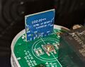 SE-341AC with the wireless module and test pads
 -
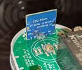 SE-341AC Module with serial connection pins exposed
 -
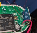 SE-341AC Module Connections


The pinouts for all 5 connections are:
| Smart plug module | Logic level converter | USB UART |
|---|---|---|
| TX | <-> | RX |
| RX | <-> | TX |
| 3.3v | 3.3V (LO) <-> 5V (HI) | 5V |
| GND | GND <-> GND | GND |
| IO0 to GND (via 10K) |
Here's what that wiring looks like.

Dumping the stock firmware
Use esptool to read the firmware. Run the following command to extract the firmware from the ESP chip.
./esptool --port /dev/ttyUSB0 --baud 115200 --chip auto read_flash 0 0x100000 lenovo2a.bin
esptool.py v3.2
Serial port /dev/ttyUSB0
Connecting....
Detecting chip type... Unsupported detection protocol, switching and trying again...
Connecting...
Detecting chip type... ESP8266
Chip is ESP8285N08
Features: WiFi, Embedded Flash
Crystal is 26MHz
MAC: c4:dd:57:22:6b:b4
Uploading stub...
Running stub...
Stub running...
1048576 (100 %)
1048576 (100 %)
Read 1048576 bytes at 0x0 in 95.9 seconds (87.5 kbit/s)...
Hard resetting via RTS pin...
After obtaining the firmware, you can extract the stock PSK key by running strings on the binary. This information might be useful for the tuya-convert community to help them potentially finding out how the PSK keys are generated.
Loading Tasmota
Download the most recent version of Tasmota from http://ota.tasmota.com/tasmota/release/. You will want to get the tasmota.bin file.
Using esptool, erase and then flash the firmware. I was unable to erase the flash for some reason, Make sure you are using the latest version of esptool.
$ esptool --port /dev/ttyUSB0 erase_flash
esptool.py v3.2
Serial port /dev/ttyUSB0
Connecting...
Detecting chip type... Unsupported detection protocol, switching and trying again...
Connecting...
Detecting chip type... ESP8266
Chip is ESP8285N08
Features: WiFi, Embedded Flash
Crystal is 26MHz
MAC: 70:03:9f:51:79:72
Uploading stub...
Running stub...
Stub running...
Erasing flash (this may take a while)...
Chip erase completed successfully in 1.1s
Hard resetting via RTS pin...

$ esptool --port /dev/ttyUSB0 write_flash -fs 1MB -fm dout 0x0 tasmota.bin
esptool.py v2.8
Serial port /dev/ttyUSB0
Connecting....
Detecting chip type... ESP8266
Chip is ESP8285
Features: WiFi, Embedded Flash
Crystal is 26MHz
MAC: c4:dd:57:24:11:8f
Enabling default SPI flash mode...
Configuring flash size...
Erasing flash...
Took 2.47s to erase flash block
Wrote 642048 bytes at 0x00000000 in 63.2 seconds (81.3 kbit/s)...
After flashing, disconnect GPIO0 and power cycle the device. It should boot and the blue LEDs should be lit. You should see the plug appear as an access point. Connect to it with your phone and configure the WiFi details on the captive portal page.
Once Tasmota is running and you're able to reach the web page on your network, desolder all the connection wires and re-assemble the plug. If your outter case is slightly mangled from the disassembly process, some hot air can be used to remold the plastic casing.
Configuring pins
The Tasmota template for this device is available at https://templates.blakadder.com/avatar_AWP04L.html. At the time of this writing, the pinouts do not have the appropriate configuration for the power monitoring feature that's available in this device and the red LED.
Through some trial and error, I was able to come up with the following template that also gets power measurement readings.
{"NAME":"Lenovo SE-341AC","GPIO":[0,321,0,32,2720,2656,0,0,320,224,2624,0,0,0],"FLAG":0,"BASE":18}
The pinouts for this plug are:
| Pin | Feature |
|---|---|
| GPIO1 | Red LED - LED_i 1
|
| GPIO3 | Button 1
|
| GPIO4 | BL0937 CF
|
| GPIO5 | HLWBL CF1
|
| GPIO12 | Blue LED - Led_i 3
|
| GPIO13 | Relay 1
|
| GPIO14 | HLWBL SEL_i
|
Since Tasmota doesn't support multiple LEDs per relay (as far as I can tell), you can either keep the blue light on all the time (by setting its LED number to 3) so that it appears magenta when on and blue when off.
Calibration
Connect a kill-a-watt or other power meter and attach a load to the plug. Use the voltageset and currentset commands to calibrate its power measurements.
I read 122 volts and 0.441 amps, so I ran the following in the console:
voltageset 122
currentset 441
If the power factor doesn't seem to agree, you can use the powerset command to set the active power reading. The active power is usually the value that your reference meter / kill-a-watt is reporting. In my case, I have a LED bulb using 53.6 watts with a power factor of ~0.9 while the smart meter is reporting 60 watts at 1.0 power factor. To correct this, I ran:
powerset 53.6
This should correct the power factor being reported down to ~0.9.
The calibration values that I ended up with for both my smart plugs were:
10:06:13.832 CMD: powercal
10:06:13.839 MQT: tasmota/SE341AC-2/stat/RESULT = {"PowerCal":10633}
10:06:15.760 CMD: currentcal
10:06:15.767 MQT: tasmota/SE341AC-2/stat/RESULT = {"CurrentCal":3490}
10:06:17.451 CMD: voltagecal
10:06:17.458 MQT: tasmota/SE341AC-2/stat/RESULT = {"VoltageCal":1673}
These smart plugs have good voltage readings even under load, unlike my older AWP04L units which reads ~10 volts under at 6 amp load.
See also
- https://templates.blakadder.com/lenovo_ZA7F0000WW.html
- https://developer.tuya.com/en/docs/iot/wifie2smodule
- A redditor who took some nice pictures of the unit's internals including the underside of the PCB - https://old.reddit.com/r/tasmota/comments/rs9svj/advice_for_flashing_lenovo_smart_plug/