Raspberry Pi: Difference between revisions
m Formatting |
|||
| Line 32: | Line 32: | ||
==== Pacman Keys ==== | ==== Pacman Keys ==== | ||
ArchLinux changed how their keys are distributed recently. When an update is attempted, Pacman will complain about the packages being invalid. Eg. | |||
{{highlight|lang=terminal|code= | {{highlight|lang=terminal|code= | ||
error: systemd-libs: signature from "Arch Linux ARM Build System <builder@archlinuxarm.org>" is unknown trust | error: systemd-libs: signature from "Arch Linux ARM Build System <builder@archlinuxarm.org>" is unknown trust | ||
Revision as of 00:35, 1 September 2019
Setup
Arch Linux
Download ArchLinux's Raspberry Pi tarball.
- Raspberry Pi: http://archlinuxarm.org/os/ArchLinuxARM-rpi-latest.tar.gz
- Raspberry Pi 2: http://archlinuxarm.org/os/ArchLinuxARM-rpi-2-latest.tar.gz
- Raspberry Pi 3: http://archlinuxarm.org/os/ArchLinuxARM-rpi-3-latest.tar.gz
- Raspberry Pi 4: http://archlinuxarm.org/os/ArchLinuxARM-rpi-4-latest.tar.gz
Setup the SD card to contain two partitions using fdisk:
- 100MB (W95 FAT32 (LBA))
- Rest: OS / Data
# fdisk /dev/sdcard
## Set up the SD card partitions
## Commands are: o, n, p, [enter], +100M, t, c, n, p, 2, [enter], [enter], w
# mkfs.vfat /dev/sdcard1
# mkfs.ext4 /dev/sdcard2
# cd /mnt
# mkdir root root/boot
# mount /dev/sdcard2 root
# mount /dev/sdcard1 root/boot
# tar -xpf ArchLinuxARM-rpi-latest.tar.gz -C root
# umount root/boot root
Once the SD card is prepared, insert it to the Pi and power it on. Log in to ArchLinux using the default user alarm using password alarm. The default root password is root.
For more information and to see the latest images see:
- http://archlinuxarm.org/platforms/armv6/raspberry-pi
- http://archlinuxarm.org/platforms/armv7/broadcom/raspberry-pi-2
Pacman Keys
ArchLinux changed how their keys are distributed recently. When an update is attempted, Pacman will complain about the packages being invalid. Eg.
error: systemd-libs: signature from "Arch Linux ARM Build System <builder@archlinuxarm.org>" is unknown trust
:: File /var/cache/pacman/pkg/systemd-libs-242.84-2-armv7h.pkg.tar.xz is corrupted (invalid or corrupted package (PGP signature)).
To fix this, run:
# pacman-key --init
# pacman-key --populate archlinuxarm
# pacman -Syu
Configuration
Wi-Fi
Wi-Fi is supported on the Raspberry Pi 3 out of the box. Older Pis will require a USB Wi-Fi dongle. Using Wi-Fi on the Pi is basically the same as on any other Linux desktop.
See the main page on Wi-Fi.
GPIO
GPIO (General Purpose Input/Output) pins can be interfaced using the GPIO Sysfs on the Linux kernel.
Without going into details, you can interface with GPIO at /sys/class/gpio with these common commands:
| Command | Description |
|---|---|
cat /sys/class/gpio/gpiochip0/ngpio
|
Returns the number of GPIOs managed by this device.
Eg. RPi 1 has More precisely, this device handles GPIOs 0 through 53 (N to N + ngpio - 1). |
cat /sys/class/gpio/gpiochip0/base
|
Returns the first GPIO number. (This should be the same as the number after gpiochipN).
|
echo 11 > /sys/class/gpio/export
|
Exports GPIO 11. Creates a device /sys/class/gpio/gpio11
|
echo in > /sys/class/gpio/gpio11/direction
|
Sets the GPIO to either in or out |
echo 0 > /sys/class/gpio/gpio11/value
|
Writes a binary value to the GPIO |
echo 11 > /sys/class/gpio/unexport
|
Removes GPIO 11. |
If you plan on doing something advance with the GIOs, you probably should use a library instead.
See also:
- https://git.kernel.org/cgit/linux/kernel/git/stable/linux-stable.git/tree/Documentation/gpio/gpio.txt
- https://git.kernel.org/cgit/linux/kernel/git/stable/linux-stable.git/tree/Documentation/gpio/sysfs.txt
I2C
The steps below assume you are on ArchLinux. If you use a different distro, some of the paths may be different on your system.
Setup
Install the i2c-tools package.
# pacman -S i2c-tools
Load the i2c modules on boot by adding the following lines to /etc/modules-load.d/raspberrypi.conf
i2c-dev
i2c-bcm2708
Enable the hardware by editing /boot/config.txt and adding:
dtparam=i2c_arm=on
Usage
To detect devices on the i2c bus, use the i2cdetect command.
Eg. To list all devices on the first i2c port, run i2cdetect -y PORT#.
# i2cdetect -y 0
'     0  1  2  3  4  5  6  7  8  9  a  b  c  d  e  f
00:          -- -- -- -- -- -- -- -- -- -- -- -- --
10: -- -- -- -- -- -- -- -- -- -- -- -- -- -- -- --
20: -- -- -- -- -- -- -- 27 -- -- -- -- -- -- -- --
30: -- -- -- -- -- -- -- -- -- -- -- -- -- -- -- --
40: -- -- -- -- -- -- -- -- -- -- -- -- -- -- -- --
50: -- -- -- -- -- -- -- -- -- -- -- -- -- -- -- --
60: -- -- -- -- -- -- -- -- -- -- -- -- -- -- -- --
70: -- -- -- -- -- -- -- --
See Also:
Control Status LEDs
The Raspberry Pi 2 (and higher) LEDs are driven by the kernel's led-GPIO drivers. This allows for the LEDs to be controlled by software rather than hardware as is the case with the older first generation Pi's. The two LEDs on the Raspberry Pi 2 are the green status light (led0) and the red power light (led1).
To see the available triggers that are in use and available for a particular LED:
# cat /sys/class/leds/led1/trigger
none usb-gadget usb-host [mmc0] timer oneshot heartbeat backlight gpio cpu0 cpu1 cpu2 cpu3 default-on transient flash torch input
The active trigger is in [ ] and can be changed by writing to the file. For example, to turn off the LED entirely:
# echo none > /sys/class/leds/led1/trigger
# cat /sys/class/leds/led1/trigger
[none] usb-gadget usb-host mmc0 timer oneshot heartbeat backlight gpio cpu0 cpu1 cpu2 cpu3 default-on transient flash torch input
You may also edit the config.txt file to change the behavior on startup.
# Disable the ACT LED.
dtparam=act_led_trigger=none
dtparam=act_led_activelow=off

# Disable the PWR LED.
dtparam=pwr_led_trigger=none
dtparam=pwr_led_activelow=off
See Also:
Miscellaneous
Getting Temperature and Voltage
To get the SoC temperature, frequency, and voltages:
$ /opt/vc/bin/vcgencmd measure_temp
temp=39.2'C

$ cat /sys/devices/system/cpu/cpu0/cpufreq/scaling_cur_freq
1500000

$ for i in core sdram_c sdram_i sdram_p ; do echo $i `/opt/vc/bin/vcgencmd measure_volts $i` ; done
core volt=1.2000V
sdram_c volt=1.2000V
sdram_i volt=1.2000V
sdram_p volt=1.2250V
A power icon will appear over the display if the input voltage is below 4.63V. An under voltage event can be found using the vcgencmd get_throttled command as well.
# vcgencmd get_throttled
throttled=0x50005
The throttled value can be read as:
| Bit | Value (hex) | Description |
|---|---|---|
| 0 | 1 | under-voltage (below 4.63V) |
| 1 | 2 | arm frequency capped (temp > 80C) |
| 2 | 4 | currently throttled |
| 16 | 10000 | under-voltage has occurred since last power on |
| 17 | 20000 | arm frequency capped has occurred since last power on |
| 18 | 40000 | throttling has occurred since last power on |
See Also: https://elinux.org/RPI_vcgencmd_usage
Controlling USB Power
Use the hub-ctrl.c project at https://github.com/codazoda/hub-ctrl.c/blob/master/hub-ctrl.c to control power going to the USB ports on the Pi.
The ports on the Pi 3 are:
| Hub : Port | Controlled Ports |
|---|---|
| 0 : 1 | Ethernet |
| 0 : 2 | All 4 USB ports, no ethernet |
| 0 : 3 | Port 4 - bottom center |
| 0 : 4 | Port 2 - top right |
| 0 : 5 | Port 3 - bottom right |
Compile the program by running gcc -lusb hub-ctrl.c. You may need gcc and the libusb-compat package.
On a Raspberry Pi 3, I got the following output:
# ./a.out -v
Hub #0 at 001:002
 INFO: individual power switching.
 WARN: Port indicators are NOT supported.
 Hub Port Status:
   Port 1: 0000.0503 highspeed power enable connect
   Port 2: 0000.0000
   Port 3: 0000.0100 power
   Port 4: 0000.0100 power
   Port 5: 0000.0100 power
Hub #1 at 001:001
 INFO: ganged switching.
 WARN: Port indicators are NOT supported.
 Hub Port Status:
   Port 1: 0000.0503 highspeed power enable connect
Control power by passing -p 0 (off) or -p 1 (on).
## -h = hub, -P = port, -p = power state
# ./a.out -h 0 -P 2 -p 1
# ./a.out -h 0 -P 2 -p 0
It looks like you lose control over the USB ports if you disable Hub #1 and it requires a reboot to restore. If you get this error, try rebooting.
# ./a.out  -h 0 -P 2 -p 1
failed to control.
: Input/output error
Other Issues
I have a Pi3 with 3 HD webcams attached. The webcams sometimes go offline for some reason and this is what I get:
# ./a.out -v
Hub #0 at 001:002
 WARN: No power switching.
 Hub Port Status:
cannot read port 1 status, Connection timed out (110)
Hub #1 at 001:001
 INFO: ganged switching.
 WARN: Port indicators are NOT supported.
 Hub Port Status:
   Port 1: 0000.0503 highspeed power enable connect
I'm unable to turn the ports off and on since it returns:
# ./a.out -h 0 -P 2 -p 0
failed to control.
: Connection timed out
dmesg also produces these errors when motion tries to capture a frame.
# dmesg
[97453.442716] uvcvideo: Failed to set UVC probe control : -110 (exp. 26).
[97458.442630] uvcvideo: Failed to set UVC probe control : -110 (exp. 26).
[97458.462633] uvcvideo: Failed to set UVC probe control : -110 (exp. 26).
[97458.482659] uvcvideo: Failed to set UVC probe control : -110 (exp. 26).
[97463.442639] uvcvideo: Failed to set UVC probe control : -110 (exp. 26).
[97463.462697] uvcvideo: Failed to set UVC probe control : -110 (exp. 26).
[97463.482758] uvcvideo: Failed to set UVC probe control : -110 (exp. 26).
Mounting /var/log as tmpfs
To reduce writes to your SD card, you may want to mount /var/log into memory.
Append to the /etc/fstab with the following line.
tmpfs /var/log tmpfs nodev,nosuid,mode=0755,size=50m 0 0
This will mount /var/log as a 50MB ramdisk. If your system is using systemd, this will break systemd-journald. To fix it, you will need to create a startup script after the mount has completed that creates the journald's directory in /var/log/journal/.
Reboot the Pi for the changes to take affect, or run mount -a which will mount the ramdisk to /var/log immediately, though you'll need to restart any services that has handles to any files there.
Why would you want to do this? To limit the amount of writes that is made to the SD card to prevent premature wearing.
UART Serial
By default, ArchLinux on the Raspberry Pi will start a getty on the UART serial port. To make use of the port, you will have to disable the getty first.
Edit /boot/cmdline.txt and remove all instances of ttyAMA0. Mine ended up looking like:
root=/dev/mmcblk0p2 rw rootwait console=tty1 selinux=0 plymouth.enable=0 smsc95xx.turbo_mode=N dwc_otg.lpm_enable=0 elevator=noop
Then, run:
systemctl disable serial-getty@ttyAMA0.service
Reboot.
If everything is working, you should be able to talk with /dev/ttyAMA0.
# stty < /dev/ttyAMA0
speed 9600 baud; line = 0;
kill = ^H; min = 100; time = 2;
-icrnl -imaxbel
-opost -onlcr
-isig -icanon -echo

# cat /dev/ttyAMA0 &
# echo hello > /dev/ttyAMA0
If you need to change the baud rate, run stty -F /dev/ttyAMA0 115200
CEC over HDMI
You can control the display that the Raspberry Pi is connected to using CEC (Consumer Electronics Control) over HDMI.
Setup
Install the libcec-rpi package.
# pacman -S libcec-rpi
This package will provide the cec-client utility.
Usage
To obtain all available CEC commands, run:
$ echo h | cec-client -s -d 1
opening a connection to the CEC adapter...

================================================================================
Available commands:

[tx] {bytes}              transfer bytes over the CEC line.
[txn] {bytes}             transfer bytes but don't wait for transmission ACK.
[on] {address}            power on the device with the given logical address.
[standby] {address}       put the device with the given address in standby mode.
[la] {logical address}    change the logical address of the CEC adapter.
[p] {device} {port}       change the HDMI port number of the CEC adapter.
[pa] {physical address}   change the physical address of the CEC adapter.
[as]                      make the CEC adapter the active source.
[is]                      mark the CEC adapter as inactive source.
[osd] {addr} {string}     set OSD message on the specified device.
[ver] {addr}              get the CEC version of the specified device.
[ven] {addr}              get the vendor ID of the specified device.
[lang] {addr}             get the menu language of the specified device.
[pow] {addr}              get the power status of the specified device.
[name] {addr}             get the OSD name of the specified device.
[poll] {addr}             poll the specified device.
[lad]                     lists active devices on the bus
[ad] {addr}               checks whether the specified device is active.
[at] {type}               checks whether the specified device type is active.
[sp] {addr}               makes the specified physical address active.
[spl] {addr}              makes the specified logical address active.
[volup]                   send a volume up command to the amp if present
[voldown]                 send a volume down command to the amp if present
[mute]                    send a mute/unmute command to the amp if present
[self]                    show the list of addresses controlled by libCEC
[scan]                    scan the CEC bus and display device info
[mon] {1|0}               enable or disable CEC bus monitoring.
[log] {1 - 31}            change the log level. see cectypes.h for values.
[ping]                    send a ping command to the CEC adapter.
[bl]                      to let the adapter enter the bootloader, to upgrade
                          the flash rom.
[r]                       reconnect to the CEC adapter.
[h] or [help]             show this help.
[q] or [quit]             to quit the CEC test client and switch off all
                          connected CEC devices.
================================================================================
The commands to control the display requires an address number. You can get the address number by running the self command.
# echo self | cec-client -s -d 1
opening a connection to the CEC adapter...
Addresses controlled by libCEC: 1
In this case, the display address number is 1.
Some common commands are:
| Command | Description |
|---|---|
# echo on ADDRESS | cec-client -s -d 1
|
Turns display on |
# echo standby ADDRESS | cec-client -s -d 1
|
Turns display off |
# echo pow ADDRESS | cec-client -s -d 1
|
Returns display status |
Cross Compiling
To cross compile for the Raspberry Pi, use the GNU ARM Embedded Toolchain available at https://launchpad.net/gcc-arm-embedded/+download.
Pi Zero (armv6)
-mcpu=arm1176jzf-s -mfpu=vfp

Pi2 (armv7)
-mcpu=cortex-a7 -mfpu=neon-vfpv4 -mneon-for-64bits
(add -mthumb for a much smaller executable).

Pi3 and Pi2 V1.2 (armv8)
-mcpu=cortex-a53 -mfpu=neon-fp-armv8 -mneon-for-64bits
(change to "march=armv8-a+crc -mfpu=neon-fp-armv8 -mtune=cortex-a53" if you need the crc extensions).

Pi3 (armv8 in 64-bit mode)
-mcpu=cortex-a53
Here's a partial tutorial on bare metal coding on the Pi 3:
Booting
The boot process requires 3 files:
- bootcode.bin - Read by ROM. Enables SDRAM and loads start.elf
- start.elf - GPU firmware and loads other files to start CPU
- config.txt - config
- fixup.dat - to use 1GB of memory
- kernel.img / kernel7.img - Application (eg. Linux kernel)
These files are available at https://github.com/raspberrypi/firmware Config.txt - https://gitweb.gentoo.org/user/srcshelton.git/tree/sys-boot/raspberrypi-firmware/files/raspberrypi-firmware-config.txt
Bare Metal
GPIO peripherals and their alternative functions can be found at:
Other docs:
- https://www.raspberrypi.org/app/uploads/2012/02/BCM2835-ARM-Peripherals.pdf
- https://www.raspberrypi.org/documentation/hardware/computemodule/RPI-CM-DATASHEET-V1_0.pdf
- https://franciscomoya.gitbooks.io/taller-de-raspberry-pi/content/es/img/cheat-full.svg
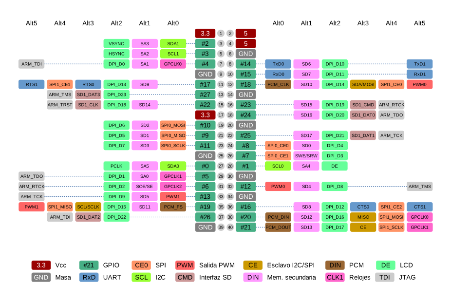
Getting JTag working on a Pi3 should just work like so:
- https://github.com/daniel-k/rpi3-aarch64-jtag/blob/master/main.c - uses ALT4 GPIOs only
- https://github.com/benpye/rpi3-armjtag/blob/master/app.c - uses ALT4 GPIO for pin 4 and the rest in ALT5 (like in CPSC labs)
Other projects:
- https://github.com/PeterLemon/RaspberryPi/
- https://github.com/brianwiddas/pi-baremetal
- https://github.com/BrianSidebotham/arm-tutorial-rpi
The cross compiler: